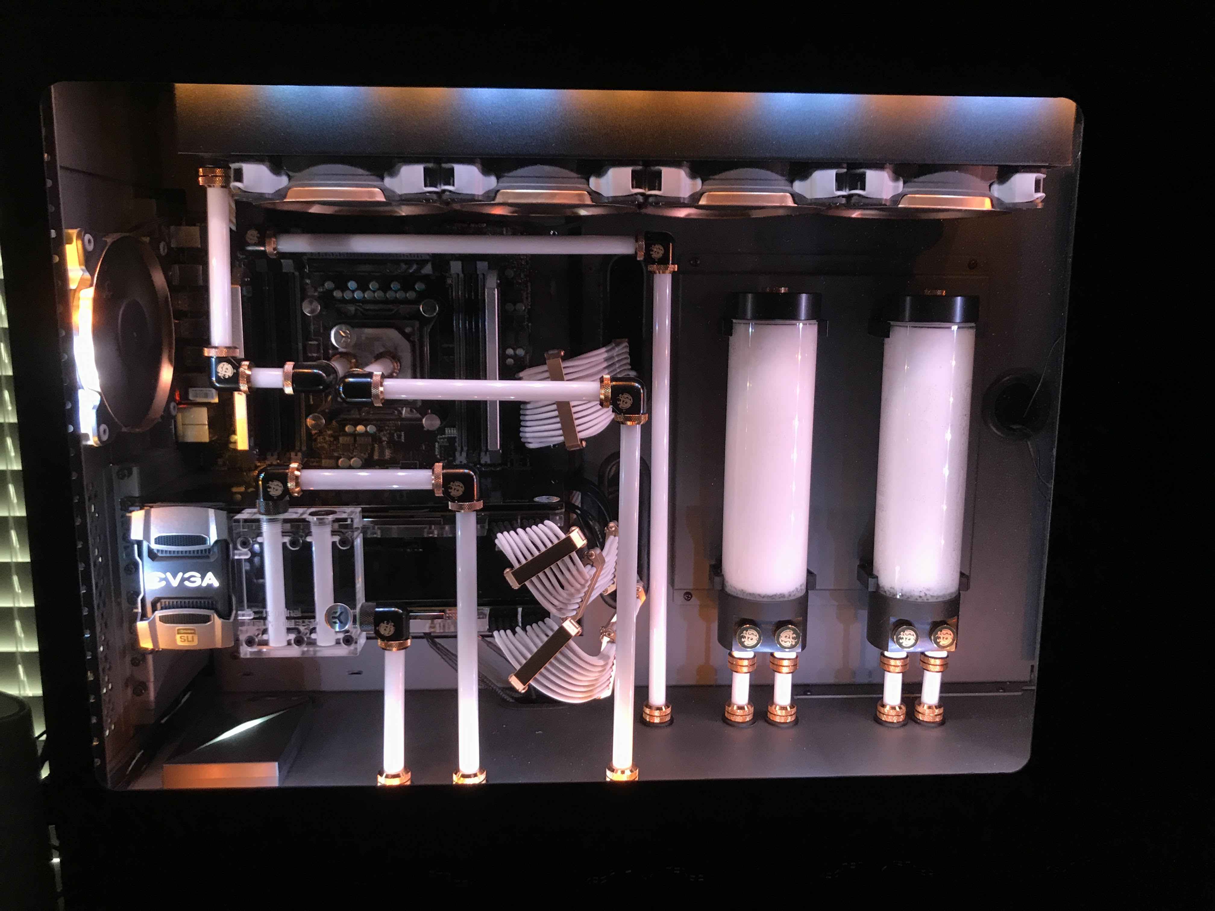
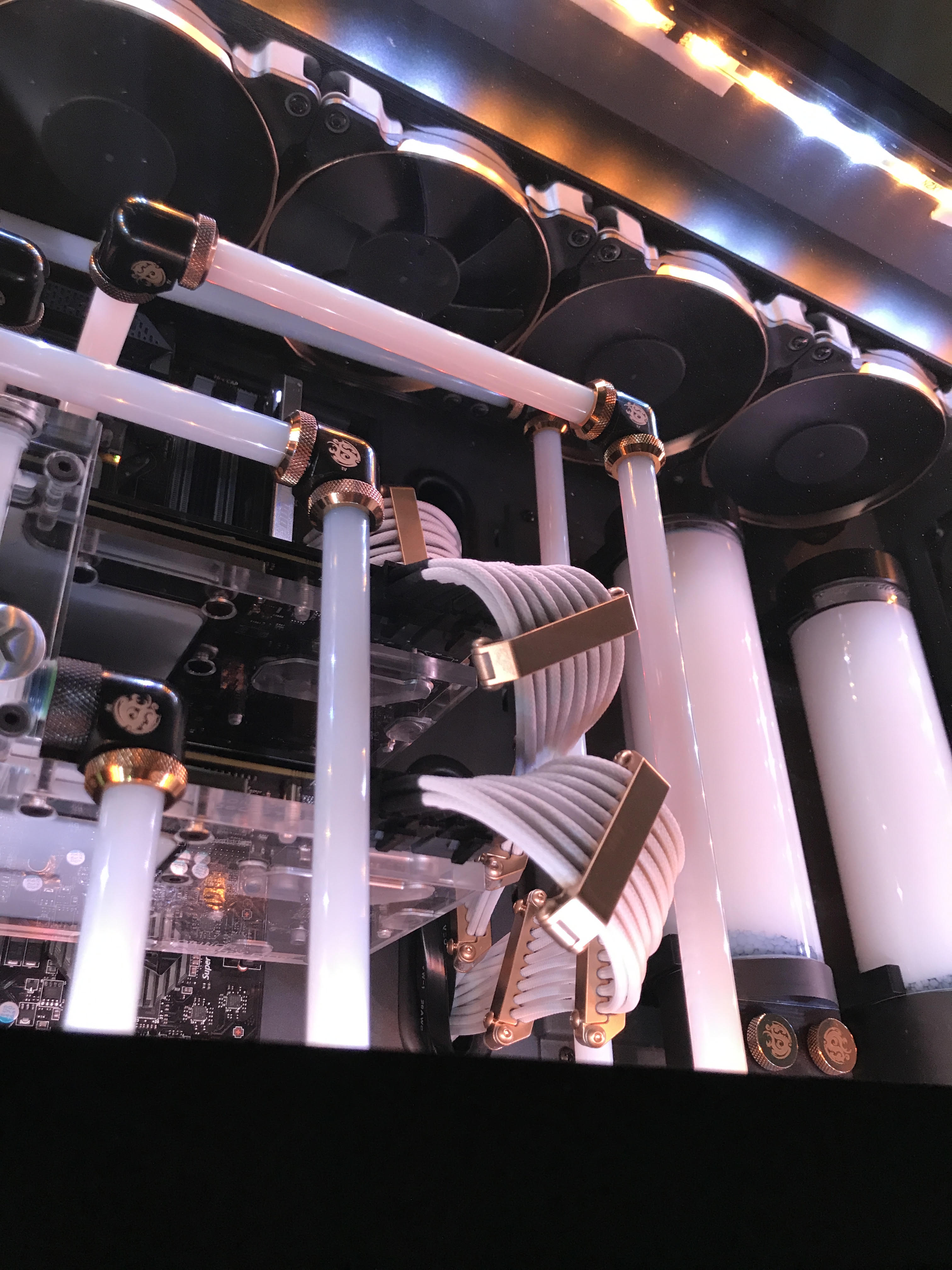
The SMA8 Watercooling Endeavour
Why?
Watercooling offers a lot of advantages in thermal performance due to the thermal density of liquid being much higher than air, and thus better at transferring heat. This means a lower fan speed can be used as the fans are only required to drive air through radiators (cooling the liquid) rather than the components heatsinks. This results in a significantly quieter system compared to air cooling. But also, why not? It looks fun!
Where to start?
There's a lot to consider for this question:
- How much radiator space is needed to remove heat from the system?
- What kind of tubing will be used? Soft? Hard?
What case can fit all the necessary components?- What case can fit all the necessary components, and is aesthetically pleasing?
After searching forums the general reccomendation is at least 140mm of radiator space per cooled component. In this system were aiming for 1 CPU and 2 GPUs; should be simple to meet. The answer to the second bullet depends a bit on the fourth, if the loop is going to be visible I prefer the look of hard (acrylic) tubing. So really the most important question is...
What case?
Enter the CaseLabs SMA8
To be fair the rationale here flies in the face of everything just discussed. It's a bit unecessary for our goal, but it will provide plenty of space to get creative and build something beautiful. The company also makes unique quality cases, which is worth supporting.
So what would a loop look like?
I like the idea of straight vertical lines. Something like...
TOP
The other great thing about the SMA8 is it comes with a "basement". We'll use this to conceal our plumbing and pumps that keep the top loop appearance clean.
BASEMENT (BOTTOM)
*The two circles on the left of the GPU pump are the connections for the bottom radiator
Supplies:
Now that we have the sketches we can plan out what we need.
- Case
- 2 Radiators - 480mm, 560mm (One for each loop)
- 2 GPU Waterblocks
- CPU Waterblock
- SLI Connector (passes liquid between two blocks)
- 2 Pumps
- 2 Reservoir
- Acrylic tubing
- Fittings (This could be a whole other post)
- The actual computer components
But wait, how are we going to get the tubes through the midplate of the computer chassis?
Passthrough Fittings!
They are threaded internally allowing fittings to be attached to both sides, we just need to drill a hole in the midplate, secure them, and we can attach fittings as regular.
Okay, another problem. How do we create the correct sized hole for the fittings?
Step bit!
Some research was required here to ascertain how to gradually increase the size of a drilled hole. The step bit allows us to seamlessly "step" up the size of our drilled hole to exactly the size of the fitting.
The next issue is how we will mount the reservoirs on the mounting plate.
The reservoirs come included with mounts, however the mounts need to screw into some source. The case has an included mounting plate but no pre-drilled holes. This means the holes we make for the mount have to be threaded to support the mounting screws, as there is no clearance for securing via nuts. This seemed like a non-starter for me, but after some more research I discovered a tool called a tap:
This creates threaded holes that can be used to secure our reservoir mounts to the mounting plate.
New items added to the supplies list:
- Step bit
- Tap
- Lube (Required for tapping)
Now we can get started!
Step 1 - Waterblock the graphics cards
Graphics cards come pre-installed with an air cooler, we need to remove this to install our waterblock.
Card with stock cooler removed:
Card with waterblock installed:
Step 2 - Mount motherboard and install CPU with waterblock
Just like any other normal heatsink
Step 3 - Mount reservoirs
Once on the mounting plate we simply screw the mounting plate into the chassis
Step 4 - Install the GPUs and Motherboard and cut tubing to fit
This is a little bit of a "draw the rest of the owl" situation here, I regrettably dont have pictures of the process. However, once all the components are installed all that is left is some measuring for the tubing and cutting the acrylic with a pipe cutter. Wear safety glasses!
Step 5 - Build the basement plumbing
The indicated drain valves attached to the pumps make draining and cleaning the system easy.
Since they live at the bottom of the loop the liquid naturally flows out.
I went with soft tubing here as its easier to manage and wont be visible.
Step 6 - Fill it with coolant
Theres a trick here to powering on the pumps without turning on the rest of the system which allows for leak testing. Any leaks wont short the components as they wont be powered. This involves bridging some connectors on the PSU 24-pin power connector to short the connection and allow the PSU to operate normally. More info here

